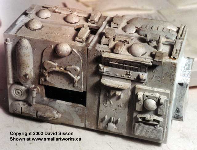
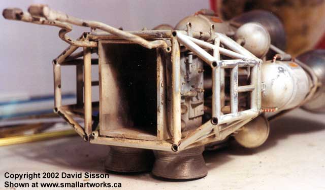
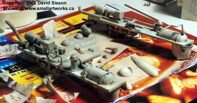
Above:
The front interior corridor with the "kitbashed" detailing. Parts from
plastic model kits were randomly glued in place to create texture.
Detailing on these sections is fairly crude
and comes from a variety of model ship and aircraft kits. Any sort of flat
kit parts, bulkheads, instrument panels, decking etc, is simply stuck on
with no attempt to blend or disguise them. One disappointment is that there's
no doorway detailing at the end next to the passenger pod, just the
faint drawn-on outline of a hatch.
With the two halves pushed back together
the kit parts on the top and bottom were gently tacked back into position
and the unit was repainted using coats of grey and white primer followed
by a bit of airbrushed weathering.
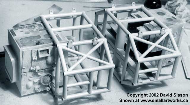
The kit parts were again removed to allow
for the reinsertion of the section back into the repainted brass cages
and then the parts were permanently glued back down. The two side shelves
were now put back into position, apart from a little bit of cleaning I
decided to leave them alone as I saw no reason to alter or repaint them.
From the start I had decided to try and
leave some parts of the model untouched to ensure that it didn't start
to look like a replica, the idea was to repair major damage (large cracks,
split frame etc) get rid of the terrible paintwork and return it to a decent
condition but not to try and remove every single blemish. The models 29
years old and the knocks it has received are like scars tracing its history
and make the model more interesting to look at, toning them down is fine
but I didn't want to remove them completely.
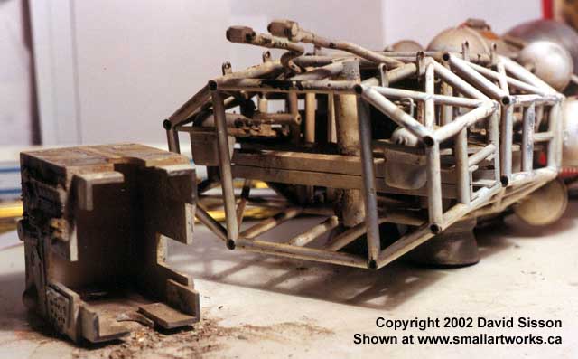
The Front cage had been easy with only
a couple of breaks to fix up but the rear had a lot of damage and was in
danger of falling apart in places .
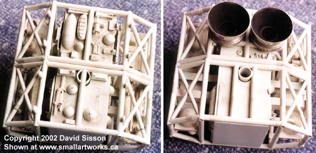
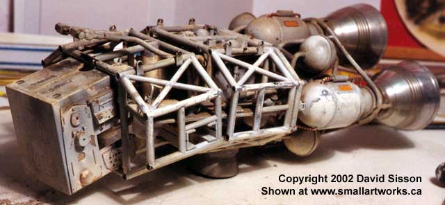
The aluminium engine bells are just held
in place by allen screws and during the first series could easily be removed
(you can see one dropping off during the crash landing scene in The Last
Sunset) but with the modifications for series two they are locked in place
by the gas feeder tubes that pierce the sides near the base, however three
of the connections are broken so these bells could be removed during the
restoration process.
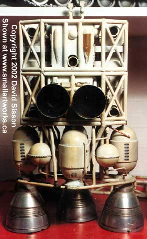
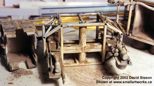
Splitting this section again began with
the removal of all the kit parts on the top and bottom panels however the
process was made more difficult by the gas feeder tubes which extend through
the cages. These tubes begin with two small inlet valves connected to copper
pipes that reside between the pipework of the spine. One tube extends straight
back to the ring pipe, which encircles the base of the four engines, connecting
at the top right side. The other works it's way downwards and connects
to the ring at the lower left side with two further dummy pipes added (bottom
right/top left) to balance out the design.
Very slowly the pieces came apart, progress
was held up by the two side shelves that had a lot more detailing on them
which jammed between the cage pipework and included connecting tubes to
the central corridor section.
As a result I had to disassemble parts
of the shelves before they would come out and stick those bits on more
double sided tape on more bits of card covered in more diagrams.
Yikes!
What a mess!
There was a point when I began to
wonder if it was all going to go back together again..........
Continued...
|