|
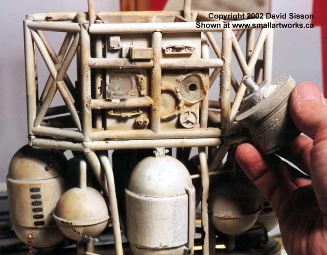
The vertical jets were now removed
to allow for the extraction of the rear corridor box section. These
were just glued into holes in the base and could be twisted free. One piece
of pipework under the jet was missing and there were kit parts in the area
it occupied which would seem to indicate that the part fell off during
the first series and was not replaced.
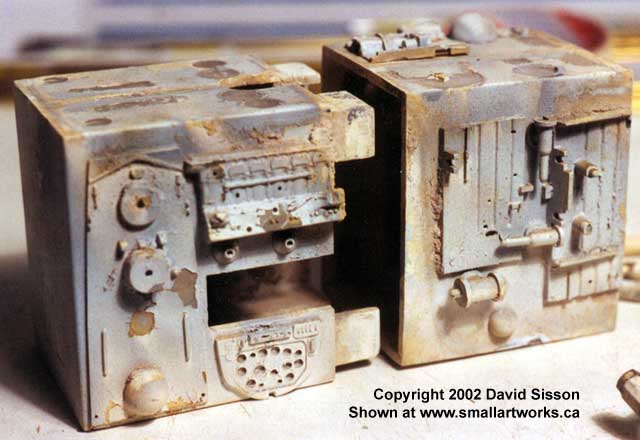
The boxes and
underside VTOLs are taken apart and cleaned...
All of the aluminium parts on the model
needed cleaning with Brasso metal polish, especially those which seemed
to be coated in a layer of concrete dust.
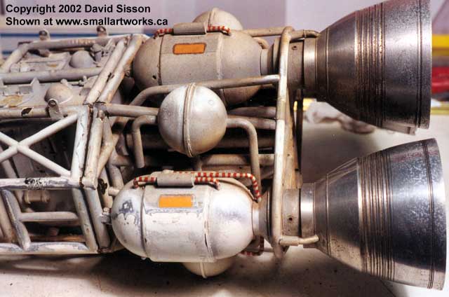
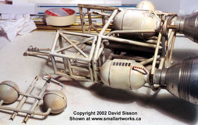
The parts of the large combustion chamber
tanks in front of the bells were all loose because they are only dressing
and not structurally sound items. The domes are EMA (a.k.a. Plastruct)
products and the middle cylinder is solid wood. The small bracket at the
front that connects to the rear cage is actually soldered to a length of
¼" brass tube that runs all the way into the base of the engine
bell, so the combustion chamber just has a hole drilled down the centre
and hangs on it. Most of the thin piping running over the surface of these
parts is just plastic coated wire, bent to shape and simply pressed into
position. These "plumbing" tubes and parts around the engine section on
the model as they exist today barely resemble the configuration that was
in place when the model was originally built. This area of the model underwent
extensive modifications throughout the run of the series.
|
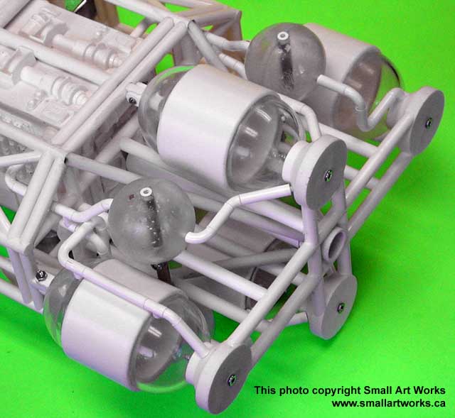
Small Art Works tech note...
Below is a picture of an unfinished
44" Eagle replica under construction by Small Art Works for a customer,
showing what the "plumbing" or piping configuration would have looked like
when the #1 Eagle model was originally built. (Special thanks to Chris
Trice and Daniel Prud'Homme for the information necessary to accurately
construct this replica.)
Now, back to David Sisson with his restoration
article...
|
One point of interest design wise is that
the top and bottom chambers don't fit properly without alteration, something
I discovered when I built a replica and thought I'd gone wrong. The middle
core butts up against the supports running between the rear cage and the
cross member frame, so two deep groves are cut into the wood to allow the
chambers to fit in place.
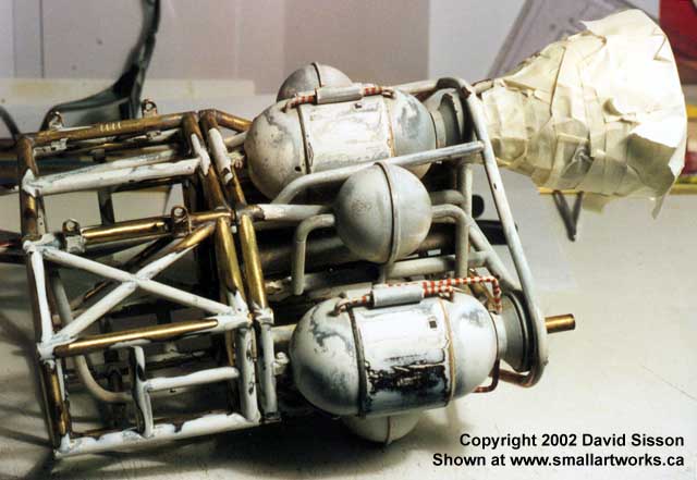
The two smaller tanks, above and below,
are again EMA domes but this time glued to a central brass disc that is
soldered to a connecting tube. The pipes coming out of the front and rear
are just lightweight plastic tubes and bends which together with many of
the parts on the shelves inside the cages can still be found in the EMA
catalogue.
With the rear corridor section and vertical
thrusters removed, the bottom framework fell out quickly followed by the
small right hand side fuel tanks. The model had obviously received a heavy
blow to this area in the past that had twisted the right engine out of
line and broke the cross member support. So many pieces of pipe were loose
on the back of the cage that I thought it might all fall apart, so I quickly
identified the most important connections and soldered them back together
again to give the unit some rigidity while I then attempted to straighten
it all up.
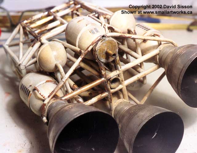
One by one all the broken joints were cleaned
of accumulated paint and soldered back together again, a job made slightly
tricky because I couldn't remove the plastic and wood combustion tanks
which did get a little bit singed in a couple of places. All the parts
fitted back in position, only one piece of brass pipe was missing and had
to be replaced, but it proved impossible to completely straighten out the
unit and there's still a few kinks in there.
Rear section almost ready for painting.
The wooden combustion chambers had a number of splits running along their
surfaces which needed filling and then smoothing over and quite a bit of
loose paint that needed chipping off. Note the four notches on the cages
upper most length of brass pipe. All four cage sections were numbered in
this manner by the original model maker.
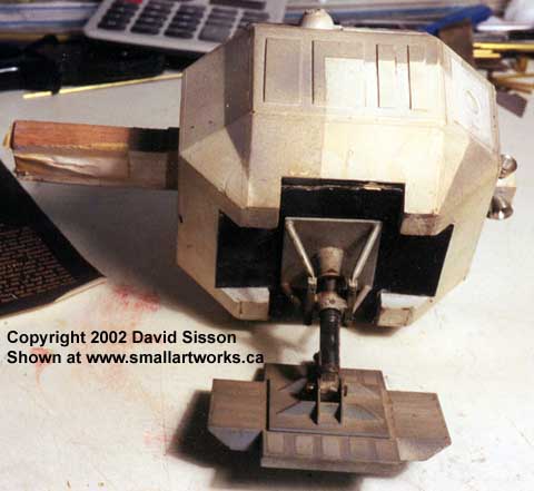
With the frame now fixed I turned my attention
to the shoulder pods. These are made from wooden blocks that are clad in
thin perspex and then detailed with grey ABS plastic sheeting and kit parts.
Over the years the action of the glue and paint has caused some of the
thin perspex panels to warp and lift away from the wood and several just
fell off.
In the past I had noticed, in some publicity
photographs, that the landing gear assemblies were occasionally twisted
and so I thought they were damaged. However these parts are simply pushed
into a hole, so they can easily rotate or be pulled out, and were just
held in position with double sided tape.
Each pod is partially hollowed out by four
large holes that are covered by a plasticard plate again attached using
tape. In the right hand hole you can just see a brass tube that runs into
the back of the attitude thruster block which can also be rotated and pulled
out.
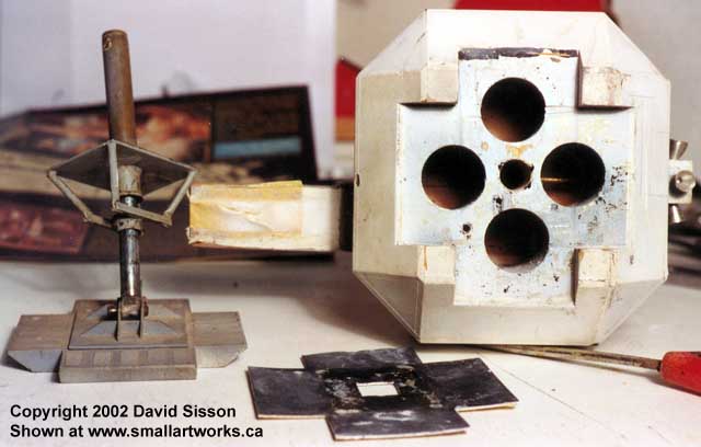
On the left hand side of the pod you can
see the wooden support that plugs into the frame. All of these are a bit
loose but this one (front left) has been sanded down in size, possibly
for the episode 'The Exiles' when it was plugged into the 2nd 44 inch Eagle
model, and it is now covered in masking tape to make it fit properly. Also
note that the four small lower corners are just painted wood and are not
covered in plastic.
Continued...
|